Difference between revisions of "MODE 3"
m |
(Remove zebra stripes.) |
||
| Line 6: | Line 6: | ||
To make the display roughly as tall as other MODEs (=256 scanlines), MODE 3 allocates 10 scanlines per text row, making 250 scanlines in all. Since the VDU routines and the hardware are designed for 8 scanlines per row, the bottom two lines are left blank, not mapped to any part of memory. As the display area is no longer ''contiguous'', the MOS disables graphics functions (all [[PLOT]] commands, [[CLG]], [[GCOL]], [[VDU 5|cursor coupling]], the [[VDU 29|graphics origin]] and [[VDU 24|graphics window]].) All other functions including [[screen editing]] operate as normal. | To make the display roughly as tall as other MODEs (=256 scanlines), MODE 3 allocates 10 scanlines per text row, making 250 scanlines in all. Since the VDU routines and the hardware are designed for 8 scanlines per row, the bottom two lines are left blank, not mapped to any part of memory. As the display area is no longer ''contiguous'', the MOS disables graphics functions (all [[PLOT]] commands, [[CLG]], [[GCOL]], [[VDU 5|cursor coupling]], the [[VDU 29|graphics origin]] and [[VDU 24|graphics window]].) All other functions including [[screen editing]] operate as normal. | ||
| − | The two blank scanlines per text row are generated by the [[6845]] [[CRTC]] under MOS programming. DISEN is lowered within these rows and so they appear black, regardless of the selected background colour. However the cursor is made to overlap the bottom line of the character and the two blank lines. The cursor simply inverts the RGB value of whatever is under it, and is therefore white in the bottom two lines. | + | The two blank scanlines per text row are generated by the [[6845]] [[CRTC]] under MOS programming. DISEN is lowered within these rows and so they appear black, regardless of the selected background colour. However the cursor is made to overlap the bottom line of the character and the two blank lines. The cursor simply inverts the RGB value of whatever is under it, and is therefore white in the bottom two lines. The zebra stripes can be closed by reprogramming the CRTC with: VDU 23;9,7;0;0;0, 23;7,22;0;0;0 which sets the number of pixel lines to 8 (ie 7+1) and moves the display down to re-centre it. |
Although 384 bytes of display memory are off screen at any one time, these are not available to programs. If used unofficially they are prone to corruption, unless the program guarantees that no [[hardware scrolling]] will occur. When hardware scrolling moves the start of display memory, the mapped area will extend right up to &7FFF and wrap around to &4000. | Although 384 bytes of display memory are off screen at any one time, these are not available to programs. If used unofficially they are prone to corruption, unless the program guarantees that no [[hardware scrolling]] will occur. When hardware scrolling moves the start of display memory, the mapped area will extend right up to &7FFF and wrap around to &4000. | ||
Revision as of 14:24, 12 January 2019
MODE 3 is a high-resolution screen MODE, introduced on the BBC Micro Model B and supported by the entire BBC series including the Archimedes. It provides an 80 × 25 monochrome character display for terminal applications, such as bulletin boards and mainframe access. It also uses slightly less memory than MODE 0.
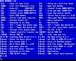
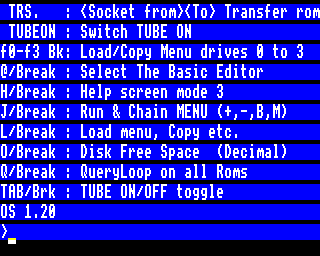
To make the display roughly as tall as other MODEs (=256 scanlines), MODE 3 allocates 10 scanlines per text row, making 250 scanlines in all. Since the VDU routines and the hardware are designed for 8 scanlines per row, the bottom two lines are left blank, not mapped to any part of memory. As the display area is no longer contiguous, the MOS disables graphics functions (all PLOT commands, CLG, GCOL, cursor coupling, the graphics origin and graphics window.) All other functions including screen editing operate as normal.
The two blank scanlines per text row are generated by the 6845 CRTC under MOS programming. DISEN is lowered within these rows and so they appear black, regardless of the selected background colour. However the cursor is made to overlap the bottom line of the character and the two blank lines. The cursor simply inverts the RGB value of whatever is under it, and is therefore white in the bottom two lines. The zebra stripes can be closed by reprogramming the CRTC with: VDU 23;9,7;0;0;0, 23;7,22;0;0;0 which sets the number of pixel lines to 8 (ie 7+1) and moves the display down to re-centre it.
Although 384 bytes of display memory are off screen at any one time, these are not available to programs. If used unofficially they are prone to corruption, unless the program guarantees that no hardware scrolling will occur. When hardware scrolling moves the start of display memory, the mapped area will extend right up to &7FFF and wrap around to &4000.
As with MODE 0, the bandwidth (pixel rate) is 16 MHz -- too high for the televisions of the day. Characters are recognisable at close range, thanks to Acorn's carefully designed character set, but a monitor is required buying for prolonged use. Compounded by the unusual tall pixels and large memory footprint for a monochrome display, few games have adopted MODE 3 and so it is used mostly for business applications -- such as terminal emulators. There is a listing in The Micro User to remove the blank lines from MODE 3, although it does not re-enable graphics.
| Type | Bitmapped, text only ('ASCII') | |
| Resolution | Text | 80 × 25 characters |
| Graphics | n/a | |
| Character size | 8 × 10 pixels, top 8 lines user definable | |
| Pixel aspect | 1:2 (tall) | |
| Bits per pixel | 1 | |
| Default palette | Logical colour | Actual colour |
|---|---|---|
| 0 | 0 (black) | |
| 1 | 7 (white) | |
| Memory | allocated | 16384 bytes |
| on screen | 16000 bytes | |
| Address range | Model B etc. | &4000..&7FFF |
| Configuration | Video ULA control register | &9C |
| Video ULA palette register file | &07 &17 &27 &37 &47 &57 &67 &77 &80 &90 &A0 &B0 &C0 &D0 &E0 &F0 | |
| CRTC register file | &7F &50 &62 &28 &1E &02 &19 &1B &01 &09 &67 &09 (from table in MOS 1.20 at &C47A..&C485) | |
| Screen display MODEs |
|---|
|
MODE 0 | MODE 1 | MODE 2 | MODE 3 | MODE 4 | MODE 5 | MODE 6 | MODE 7 |
-- beardo 14:12, 16 September 2006 (BST)

