Difference between revisions of "VDU 24"
m (1 revision) |
m (1 revision) |
(No difference)
| |
Revision as of 01:13, 8 March 2015
Defines the graphics window.
| Syntax | VDU 24,<numeric>;<numeric>;<numeric>;<numeric>;
|
| Character stream (hex) | 18 <leftL> <leftH> <bottomL> <bottomH> <rightL> <rightH> <topL> <topH>
|
| Description | Confines subsequent graphics to a rectangular window with the specified coordinates. |
Description
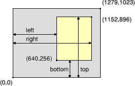
VDU 24 defines a rectangular graphics window inside which all future graphics will be plotted. The coordinate system does not change and the screen contents are not changed.
The graphics cursor can move outside the window and PLOT commands proceed as before, but only the parts lying within the rectangle are drawn.
The window limits are specified in the order left, bottom, right, top. They can also be read as the X and Y coordinates of the bottom left point, followed by those of the top right point of the window. They are taken relative to the current graphics origin; if this changes later, the window stays in the same place on the screen.
The window borders are inclusive, and are rounded up to a whole pixel. If one enters, for instance:
MODE 4
VDU 24,640;256;1152;896;
then the graphics window includes columns 640 to 1155 and rows 256 to 899 (since in MODE 4 there are four graphics units per pixel in both directions.)
Note the semicolons in the VDU statement including one at the end, as the coordinates are two-byte quantities.
