Difference between revisions of "MODE 9"
m (→MODE 9 - 10x25x16) |
|||
| Line 98: | Line 98: | ||
The MODE 9 code adapts the [[MODE 6]] screen to provide a 10 × 25 text display in 16 colours. | The MODE 9 code adapts the [[MODE 6]] screen to provide a 10 × 25 text display in 16 colours. | ||
The MOS does not allow complete support of this MODE and some bugs can be seen: for instance, | The MOS does not allow complete support of this MODE and some bugs can be seen: for instance, | ||
| − | [VDU 28|text windows]] do not work correctly. | + | [[VDU 28|text windows]] do not work correctly. |
{| class="wikitable" style="text-align:left" | {| class="wikitable" style="text-align:left" | ||
| Line 220: | Line 220: | ||
LDA #20:JSR OSWRCH \ Reset palette | LDA #20:JSR OSWRCH \ Reset palette | ||
LDA #154:LDX #128:JSR OSBYTE \ Cursor width | LDA #154:LDX #128:JSR OSBYTE \ Cursor width | ||
| − | |||
==See Also== | ==See Also== | ||
Revision as of 21:17, 12 October 2016
MODE 9 - 40x32x16
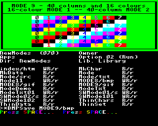
MODE 9 is a medium-resolution screen MODE, selectable with the *MODE command or the NewModes sideways ROM module, that replicates the dunctionality of the native RISC OS MODE 9.[1]
The MODE 9 code adapts the MODE 2 screen to provide a 4-colour version of MODE 1, 40 × 32 characters in 4 colours. It does this by redefining the character set to provide thin characters.
| Type | Bitmapped | |
| Resolution | Text | 40 × 32 characters |
| Graphics | 160 × 256 | |
| Character size | 4 × 8 pixels | |
| Pixel aspect | 2:1 (wide) | |
| Bits per pixel | 2 | |
| Default palette | Logical colour | Actual colour |
|---|---|---|
| 0 | 0 (black) | |
| 1 | 1 (red) | |
| 2 | 3 (yellow) | |
| 3 | 7 (white) | |
| Memory | allocated | 20480 bytes |
| on screen | 20480 bytes | |
| Address range | Model B etc. | &3000..&7FFF |
| Configuration | Video ULA control register | &D4 |
| Video ULA palette register file | &07 &17 &26 &36 &47 &57 &66 &76 &84 &94 &A0 &B0 &C4 &D4 &E0 &F0 | |
| CRTC register file | &3F &28 &31 &24 &26 &00 &20 &22 &01 &07 &67 &08 | |
MODE 9 can be created manually with the following code running in the I/O processor.
   BASIC:
   MODE 2     :REM Base MODE
   ?&30A=39   :REM Characters per line
   ?&34F=8    :REM Bytes per character
   *FX154,212

   6502:
   LDA #22:JSR OSWRCH
   LDA #02:JSR OSWRCH           \ Base MODE
   LDA #&27:STA &30A            \ Characters per line
   LDA #&08:STA &34F            \ Byte per character
   LDA #154:LDX #212:JSR OSBYTE \ Cursor width
The character set needs to be redefined to be four pixels wide, such as with the one used with NewModes.
MODE 9 - 10x25x16
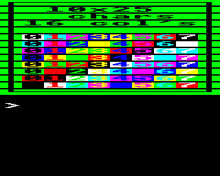
MODE 9 is also the unofficial title of an ultra-low resolution screen MODE, developed by Ian Robertson and published in The Micro User magazine (November 1985, p.123). It works on the BBC Micro but not the Electron, or the Archimedes where MODE 9 is the official 16-colour version of MODE 1).
The MODE 9 code adapts the MODE 6 screen to provide a 10 × 25 text display in 16 colours. The MOS does not allow complete support of this MODE and some bugs can be seen: for instance, text windows do not work correctly.
| Type | Bitmapped, text only ('ASCII') | |
| Resolution | Text | 10 × 25 characters |
| Graphics | n/a | |
| Character size | 8 × 10 pixels, top 8 lines user definable | |
| Pixel aspect | 4:1 (wide) | |
| Bits per pixel | 4 | |
| Default palette | Logical colour | Actual colour |
|---|---|---|
| 0 | 0 (black) | |
| 1 | 1 (red) | |
| 2 | 2 (green) | |
| 3 | 3 (yellow) | |
| 4 | 4 (blue) | |
| 5 | 5 (magenta) | |
| 6 | 6 (cyan) | |
| 7 | 7 (white) | |
| 8 | 8 (flashing black/white) | |
| 9 | 9 (flashing red/cyan) | |
| 10 | 10 (flashing green/magenta) | |
| 11 | 11 (flashing yellow/blue) | |
| 12 | 12 (flashing blue/yellow) | |
| 13 | 13 (flashing magenta/green) | |
| 14 | 14 (flashing cyan/red) | |
| 15 | 15 (flashing white/black) | |
| Memory | allocated | 8192 bytes |
| on screen | 8000 bytes | |
| Address range | Model B etc. | &6000..&7FFF |
| Configuration | Video ULA control register | &80 |
| Video ULA palette register file | &07 &16 &25 &34 &43 &52 &61 &70 &8F &9E &AD &BC &CB &DA &E9 &F8 | |
| CRTC register file | &3F &28 &31 &24 &1E &02 &19 &1B &01 &09 &67 &09 (from table in MOS 1.20 at &C492..&C49D) | |
MODE 9 can be created manually with the following code running in the I/O processor.
   BASIC:
   MODE 6     :REM Base MODE
   ?&30A=9    :REM Characters per line
   ?&34F=32   :REM Bytes per character
   ?&360=15   :REM Number of colours
   ?&361=1    :REM Pixels per byte
   ?&362=&AA  :REM Pixel left mask
   ?&363=&55  :REM Pixel right mask
   VDU 20     :REM Reset palette
   *FX154,128

   6502:
   LDA #22:JSR OSWRCH
   LDA #06:JSR OSWRCH           \ Base MODE
   LDA #&09:STA &30A            \ Characters per line
   LDA #&20:STA &34F            \ Byte per character
   LDA #&0F:STA &360            \ Number of colours
   LDA #&01:STA &361            \ Pixels per byte
   LDA #&AA:STA &362            \ Pixel left mask
   LDA #&55:STA &363            \ Pixel right mask
   LDA #20:JSR OSWRCH           \ Reset palette
   LDA #154:LDX #128:JSR OSBYTE \ Cursor width
See Also
References
| Screen display MODEs |
|---|
|
MODE 0 | MODE 1 | MODE 2 | MODE 3 | MODE 4 | MODE 5 | MODE 6 | MODE 7 |
Jgharston (talk) 17:22, 12 October 2016 (UTC) beardo 12:52, 20 September 2006 (BST)

